Image Filter from Scratch - Pure Math and Coding
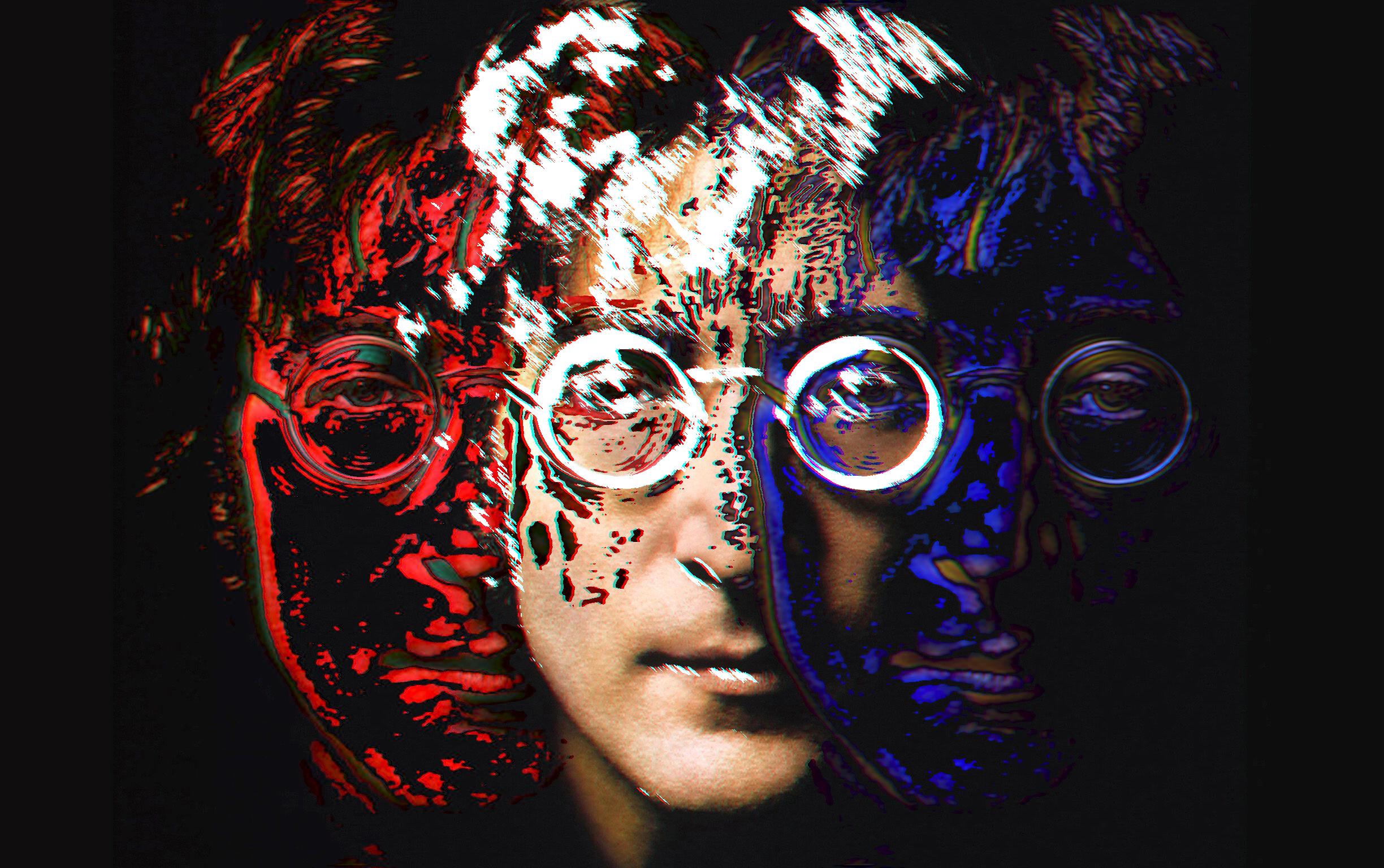
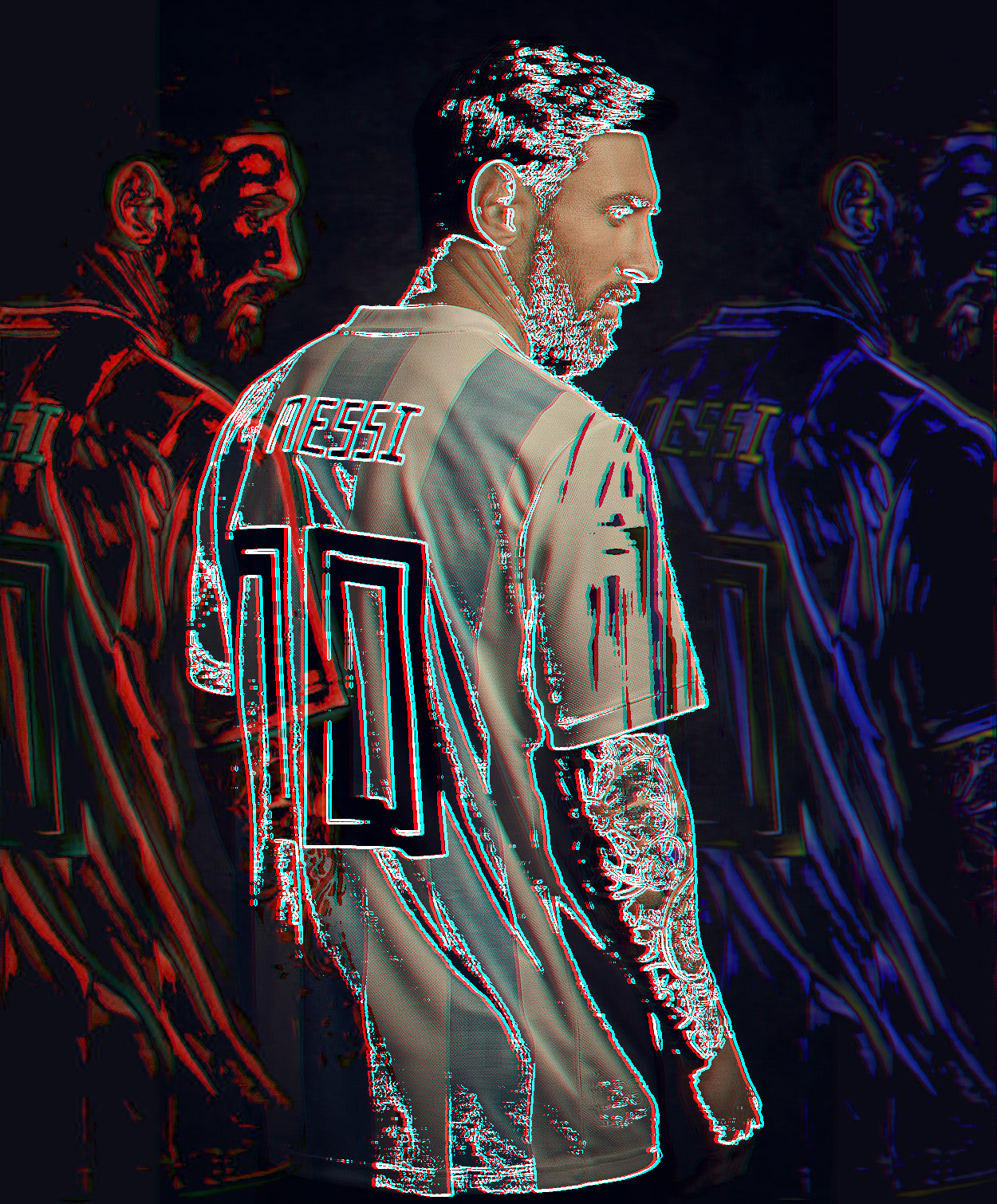
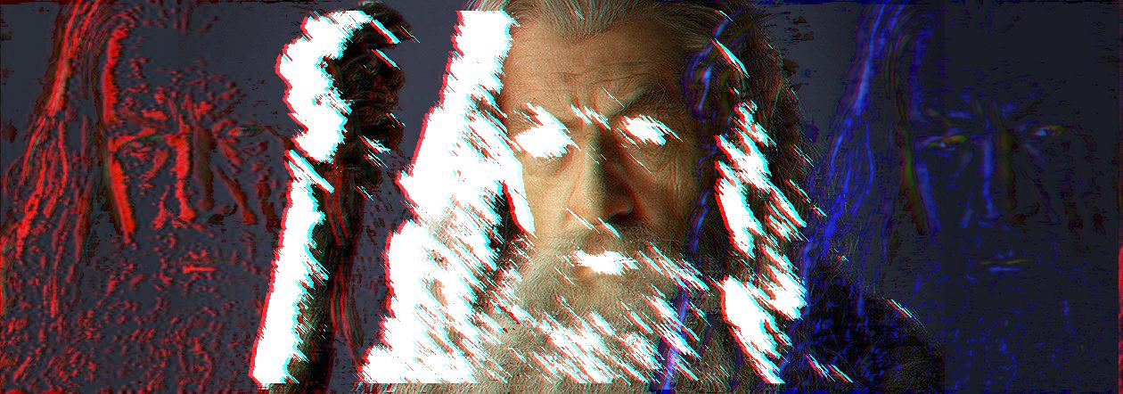
Input Images
Filter Development Process
First of all, I needed to expand my original input for the sliding operations that I would perform in subsequent processes, and for this I followed the following method: First, I kept the pixel value at the top of the left and right edges of my original image and added a ten-pixel padding on both sides, and then I added this I assigned the pixel value I kept to the pixel values in the ten padded columns. Then, I put these ten columns and the previous ten columns (the last 10 columns of the original image) into the Gaussian Blur filter to remove the obvious frequency transition. For this process, I iterated until there was an expansion of 1200 pixels on the left and 1200 pixels on the right, and finally I applied Gaussian Blur separately for the padding areas on the left and right and applied the results to the original image.
First, I passed the images that I would use for padding through the
Gaussian Blur filter and then added them to the original image.
As a second step, I divided the expanded image, which was the output of the first step, into color channels and then applied Fourier Transform to these channels, thus pulling my channels into the frequency space. Then, I applied Bandpass Filter to these channels separately, so that the frequencies in the range I specified were filtered, and then I pulled each channel back from the frequency domain to the image domain with Inverse Fourier Transform. Then, I set a threshold to eliminate pixel values close to black in the resulting image and recorded the pixels above this value in an array. I also wrote a function to apply Gaussian Blur to each of my filters, the purpose of which was to reduce the detail in my FT images. After this point, I overlapped the pixel values I kept in my array with the expanded image, shifting 2000 pixels to the left and 2000 pixels to the right. (In my left-hand filter, I applied Gaussian Blur to those outside the red channel, my aim was to preserve the red color, and in the right one, I applied the same process for blue)
In this step, I developed an algorithm to apply a Canny Filter to my original image. First, I applied Gaussian Blur to purify the image from relatively unnecessary noise that I did not want to be perceived as edges. Then, I applied a Sobel Filter to this blurred output so that I could remove the Gradient Magnitudes of my image. In this way, I would be able to obtain information where there were sharp frequency transitions. Then I applied Non Maximum Suppression, the purpose of which was to keep it if a pixel had a higher gradient value than its neighboring pixels, otherwise set it to zero. Then I set a threshold again and set it to 255 or 128 pixels, depending on the size of the gradient. Thus, I established a hierarchy between the edges.
At this stage of my project, I wanted to make a morphology application based on the neighborhood of pixels, because the two images passing through the Canny Filter did not have very similar information, and I thought the solution to this was to make a morphology study based on edges. In this application, if a pixel is higher than the threshold value I have determined (a value close to white), all 8 neighbors of that pixel will be examined and if all eight neighbors are higher than or equal to the threshold value, this will be added to the region mask. Thus, we have the opportunity to focus only on the edges of the noisy image coming from the Canny Filter. I made this morphology study recursive, gave the output of the first morphology as the input of the second morphology, and the result I got was quite satisfactory in both images.
In this step, I took the output of the previous step and collected the white and near-white pixel values in the image into an array. Then, I overlapped this array on two images consisting of only pixels with a value of 0, which were the same size as the original image. At the same time, I overlapped this array with the image output of my Fourier Transform, shifting it by +1200. I collected the white pixels in my morphology output into an array and sent the image that I overlapped to a black image to my Motion Blur filter. This filter applies convolution to the image with the kernel size I specify, but while doing this, it multiplies the pixels linearly by tangent 45 and as a result, we create a blurred image as if it were a result of movement.
In this step, we find the non-black pixels in the image we created with the motion blur filter and place them in an array. The purpose of this is, as we know from the image output of the motion blur filter, that the object that creates the moving image is actually the edges coming from the morphology output, and with the motion blur effect, a shift from white to shades of gray occurs. For this reason, I will set a threshold and use this “moving” region to overlap the next image into an array.
Finally, I overlapped the array I created in the previous step with the image I created before and shifted the pixels in this array to the right by +1200 pixels because the image I overlapped was the image I created as a result of an overlap in the previous steps. (FT and Canny-Morphology overlap) Finally, I shifted the red channel of the resulting image to the left by -5 pixels. Thus, I completed the last step of my filter application.
Other examples besides reference images:


