AMPLITUDE MODULATOR AND DEMODULATOR - PLC SIMULATION
What is Modulation
Amplitude Modulation is actually a term we are all familiar with. This method, which allows us to multiply the message signal with a much higher frequency signal in the spatial domain and transmit this message to longer distances, is just the technical manifestation of the AM expression we see on radios.
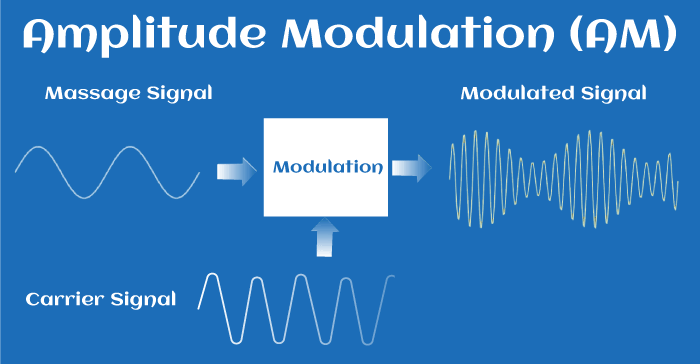
What is Demodulation
Demodulation is a technique that allows us to convert the high-frequency, high-amplitude signal modulated with the carrier signal back into the original message signal. In this method, the modulated signal is multiplied again with the carrier signal and then passed through a low-pass filter, and as a result, we synthesize a signal with properties very close to our original signal.
This block diagram represents our modulation and demodulation processes:
Let's create a message and a carrier signal and apply the operations we mentioned to these signals, first in the spatial domain and then in the frequency domain, according to their needs.
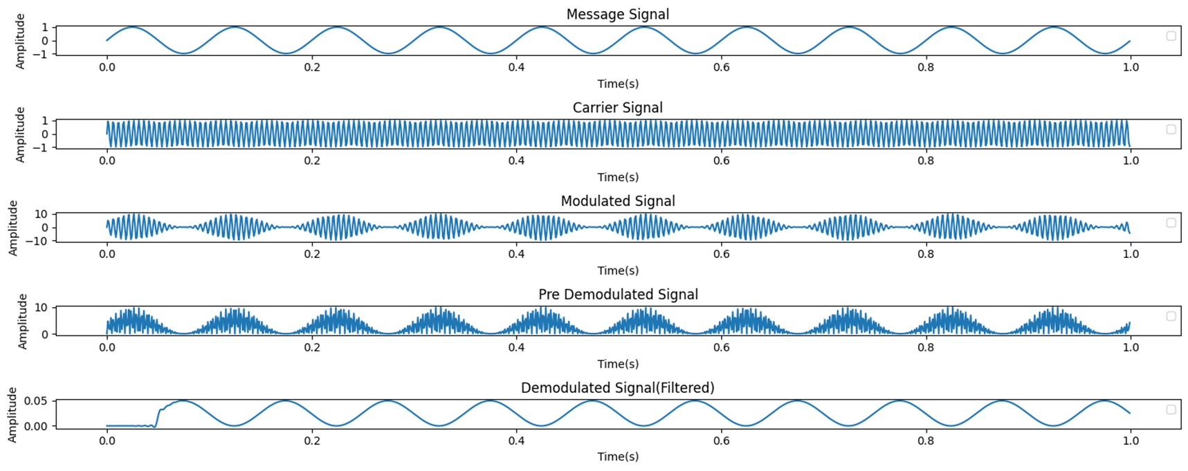
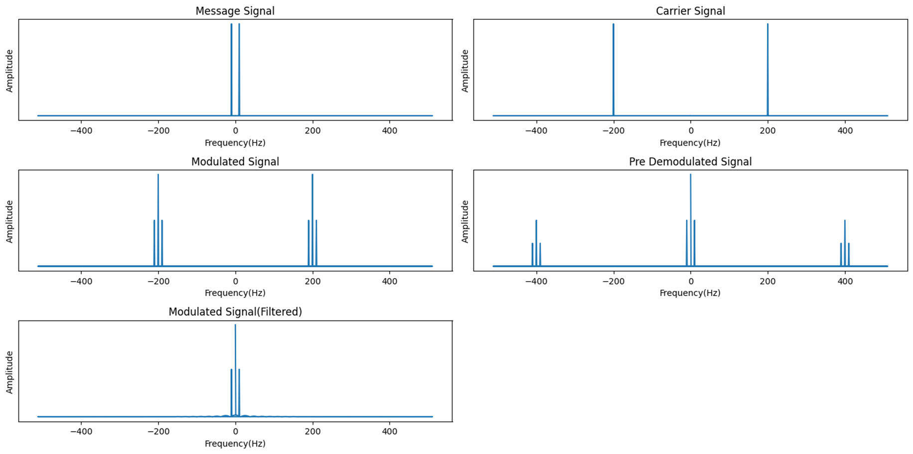
Now if we are ready, we can start the Codesys presentation.
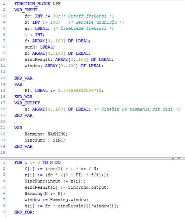
First of all, I would like to show the function blocks I use in the project:
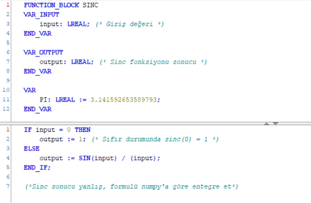
I used Sinc Function in low pass filter design.
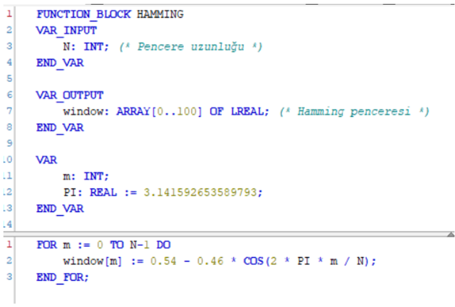
I used Hamming Window to make the results from the Sinc Function cleaner and normalized.
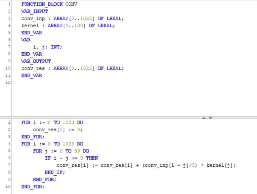
Since we are in the spatial domain, I can only use my filter on the signal by convolving it, so the convolution function I created is:
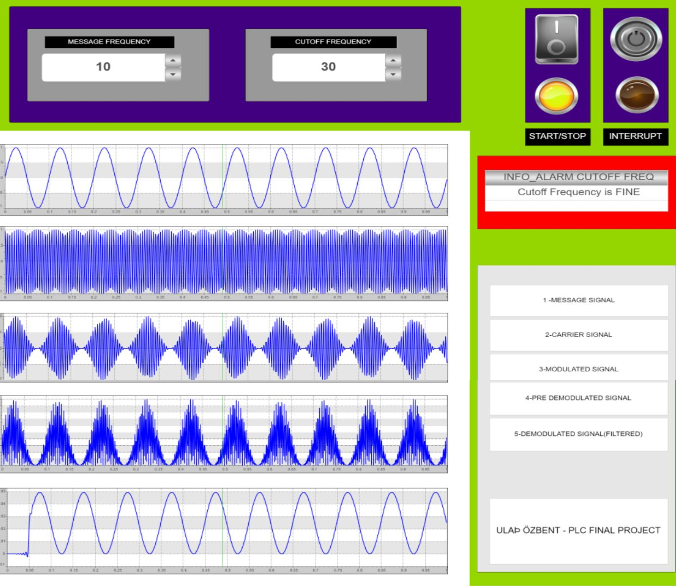
Here is my PLC HMI:
